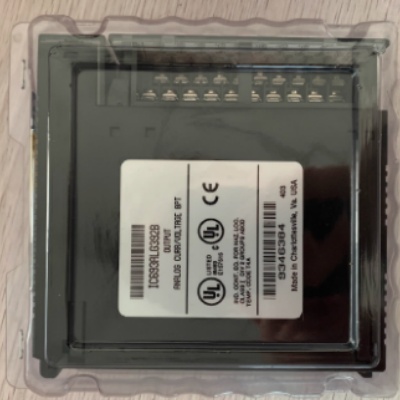
GE IC693MDL340 Output Module
General info
| Manufacture | GE |
| Item No | IC693MDL340 |
| Article number | IC693MDL340 |
| Series | GE FANUC |
| Origin | United States(US) |
| Dimension | 180*180*30(mm) |
| Weight | 0.9 kg |
| Customs Tariff Number | 85389091 |
| Type | Output Module |
Detailed data
GE IC693MDL340 Output Module
The 120 volt, 0.5 amp AC output module provides 16 output points divided into two isolated groups of 8 points each. Each group has a separate common (the two commons are not connected together inside the module). This allows each group to be used on a different phase of the AC supply or to be powered from the same supply. Each group is protected by a 3 amp fuse and each output is equipped with an RC snubber to protect against transient electrical noise on the supply line. The module provides high inrush current, making the outputs suitable for controlling a variety of inductive and incandescent loads. The user must provide the AC power used to operate the loads connected to the outputs. The module requires an AC power source.
The LED indicators that provide the on/off status of each point are located on the top of the module. There are two horizontal rows of LEDs with 8 green LEDs in each row and one red LED in the middle and right side of the two rows. This module uses two rows of green LEDs, labeled A1 to 8 and B1 to 8, for output status. The red LED (labeled F) is a blown fuse indicator and will illuminate if any one of the fuses is blown. A load must be connected to the blown fuse for the indicator to illuminate. The insert is located between the inner and outer surfaces of the hinged door. The surface facing the inside of the module (when the hinged door is closed) has the circuit wiring information and the circuit identification information can be recorded on the outer surface. The outer left edge of the insert is coded red to indicate a high voltage module. This module can be installed in any I/O slot of a 5-slot or 10-slot backplane in a 90-30 Series PLC system.
Output Calculations for Discrete Output and Combination Modules:
The output circuits of discrete solid-state output modules and combination I/O modules require two calculations, one for the module's signal level circuitry, which was already done in Step 1, and one for the output circuitry. (Relay output modules do not require this output circuit calculation.) Since the solid-state output switching devices in these modules drop a measurable voltage, their power dissipation can be calculated. Note that the power dissipated by the output circuitry comes from a separate power supply, so it is not included in the figure used to calculate the PLC power supply dissipation in Step 2.
To calculate output circuit power dissipation:
-In the Chapters 7 or 8, find the value for the Output Voltage Drop for your particular Output or Combination I/O module.
- Get the current value required by each device (e.g. relays, pilot lights, solenoids, etc.) connected to the module output points and estimate its "on time" percentage. To get the current value, consult the device manufacturer's documentation or electronic catalog. Someone familiar with how the device operates or will operate can estimate the on time percentage.
-Multiply the Output Voltage Drop times the current value times the estimated percent of on–time to arrive at average power dissipation for that output.
- Repeat this for all outputs on the module. To save time, you can determine if the current draw and on-time of several outputs are similar so that you only have to do the calculation once.
-Repeat these calculations for all Discrete Output modules in the rack.


