

GE IS2020RKPSG2A VME RACK POWER SUPPLY MODULE
General info
| Manufacture | GE |
| Item No | IS2020RKPSG2A |
| Article number | IS2020RKPSG2A |
| Series | Mark VI |
| Origin | United States(US) |
| Dimension | 180*180*30(mm) |
| Weight | 0.9 kg |
| Customs Tariff Number | 85389091 |
| Type | VME Rack Power Supply Module |
Detailed data
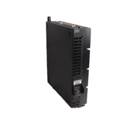
GE IS2020RKPSG2A VME Rack Power Supply Module
The VMErack power supply is mounted on the side of the VME control and interface module. It provides +5, ±12, ±15 and ±28V DC to the VME backplane and provides an optional 335 V DC output for powering flame detectors connected to the TRPG. There are two power input voltage options, one is a 125 V DC input supply, supplied by the Power Distribution Module (PDM), and the other is a low voltage version for 24V DC operation. The power supply is mounted on a sheet metal bracket on the right side of the VME rack. The DC input, 28 V DC output, and 335 V DC output connections are located on the bottom. Newer designs also have a status connector on the bottom. The two connectors on the top of the assembly, PSA and PSB, mate with the cable harness that delivers power to the VME rack.
Frequently asked questions about the product are as follows:
-What are the input/output voltage and current specifications of the power module?
The input voltage range is 85-264V AC or -48V DC, and the outputs are mostly +5V, ±12V, +3.3V, etc.
-Is it compatible with all VME racks?
It complies with the VME bus standard, but it is necessary to confirm whether the backplane power interface and mechanical dimensions of the rack match.
-How to install or replace the module?
Insert the VME slot after powering off and ensure that the rails are aligned. Secure the front panel of the module with screws. Connect the input power line and the load line.


